Components Required
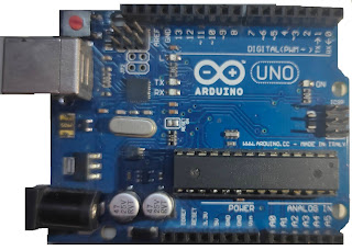
- Arduino Uno:
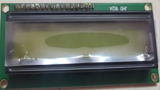
- 16x2 LCD Display:
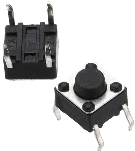
- 2 x Toggle Switches
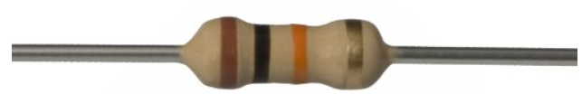
- 2 x 10K Resistors
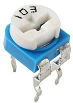
- 10K Preset
About 16x2 LCD Display
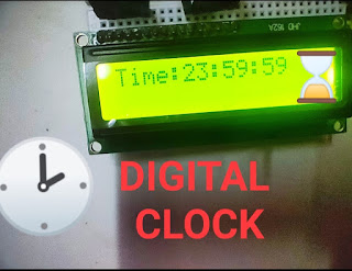
The name "16x2 LCD display" comes from the fact that it has 16 columns and 2 rows, meaning we can display 32 characters on this screen. Characters can be alphabets, numbers, or custom-made characters. Each column is made from a 5x8 matrix of pixels (40 pixels per column).
- Operating voltage: 4.7V to 5.3V
- Current consumption: 1mA without backlight
- Alphanumeric display: can show alphabets and numbers
- Works in both 8-bit and 4-bit mode
- Available in Green and Blue backlight
Pinouts
- 1. Vss: Connect to GND
- 2. Vdd: +5V (4.7V–5.3V)
- 3. VEE: Contrast adjustment
- 4. RS: Command/data register
- 5. R/W: Normally GND (write mode)
- 6. Enable: Activates read/write
- 7. Data bit 0:- To microcontroller to send 8 bit data
- 8. Data bit 1:- To microcontroller to send 8 bit data
- 9. Data bit 2:- To microcontroller to send 8 bit data
- 10. Data bit 3:- To microcontroller to send 8 bit data
- 11. Data bit 4:- To microcontroller to send 4/8 bit data
- 12. Data bit 5:- To microcontroller to send 4/8 bit data
- 13. Data bit 6:- To microcontroller to send 4/8 bit data
- 14. Data bit 7:- To microcontroller to send 4/8 bit data
- 15. LED+: Backlight
- 16. LED-: Backlight
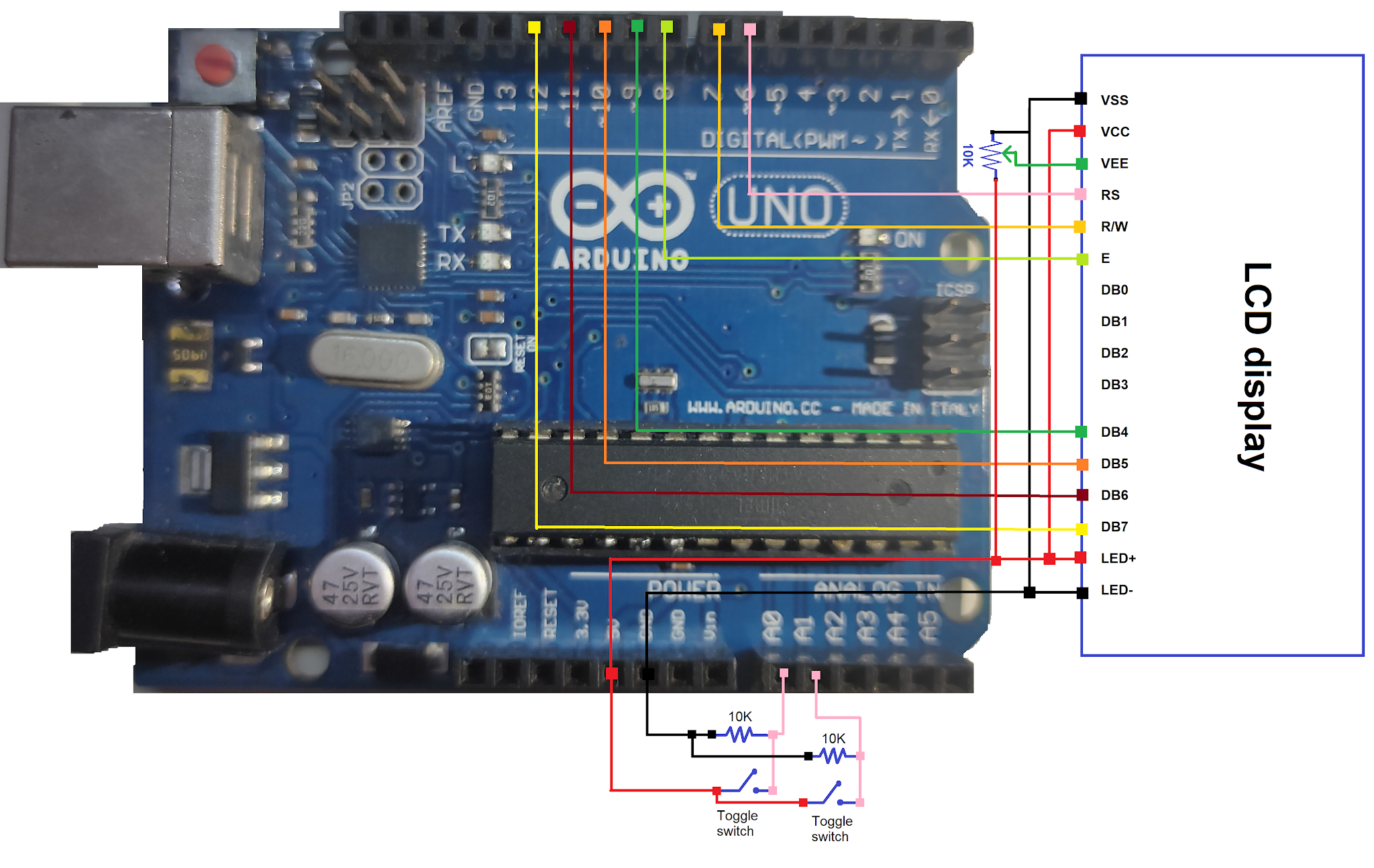
LCD Display Interfacing with Arduino
VSS and LED- are grounded. VCC and LED+ connect to Arduino’s 5V. A Preset is connected to VEE to adjust contrast. LCD pins are connected as follows:
- 1. VSS and LED- pin of LCD are combined together and are grounded.
- 2. VCC and LED+ pin of LCD are combined together and is connected to 5v pin of Arduino.
- 3. Then connect a Preset to VEE to adjust the contrast of LCD by varying the knob of Preset.
- 4. Then connect RS pin of LCD to 6th pin of Arduino and R/W pin of LCD to 7th pin of Arduino.
- 5. Then connect E pin of LCD to 8th pin of Arduino.
- 6. Then connect DB4 pin of LCD to 9th pin of Arduino, DB5 pin to 10th pin , DB6 pin to 11th pin and DB7 to 12th pin of Arduino.
- 7. Connect 1 terminal of toggle switch to 5 V and it's other terminal to A0 pin.
Toggle switch connections:
- Connect 1 terminal of resistor to GND and other to A0 pin of Arduino.
- Similarly, connect 1 terminal of toggle switch to 5 V and it's other terminal to A1 pin and 1 terminal of resistor to GND and other to A1 pin of Arduino.
Circuit Diagram
Arduino Code
#include <LiquidCrystal.h>
LiquidCrystal lcd(6, 7, 8, 9, 10, 11, 12);
unsigned long currentTime = 0, previousTime = 0;
int seconds = 0, minuites = 0, hours = 0, setmins = A0, sethrs = A1;
void setup()
{
  pinMode(setmins, INPUT);
  pinMode(sethrs, INPUT);
  lcd.begin(16, 2);
}

void loop()
{
  currentTime = millis();
  if (currentTime - previousTime >= 1000)
  {
    lcd.clear();
    previousTime = currentTime;
    seconds++;
  }
  if (seconds == 60)
  {
    minuites++;
    seconds = 0;
  }
  if (minuites == 60)
  {
    hours++;
    minuites = 0;
  }
  if (hours == 24)
  {
    hours = 0;
  }
  lcd.setCursor(0, 0);
  lcd.print("Time:");
  lcd.print(hours);
  lcd.print(":");
  lcd.print(minuites);
  lcd.print(":");
  lcd.print(seconds);
  if (digitalRead(setmins) == HIGH)
  {
    minuites++;
    while (digitalRead(setmins));
  }
  if (digitalRead(sethrs) == HIGH)
  {
    hours++;
    while (digitalRead(sethrs));
  }
}